Page 4
Here is a closeup picture of the phasing line and feedpoint attached to the underside of the boom.
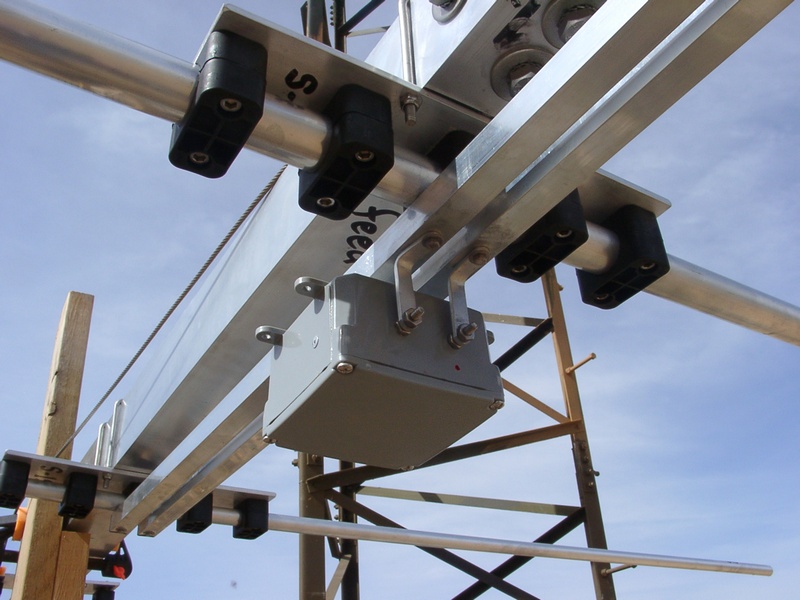
The elements attach quite easily to the boom. Each element has a center section that mounts into its respective saddle, and then the outer portions of each element are inserted into those. I used a lubricating anti-oxidant on all joints, and spray painted the elements and boom after everything was in place.
The base of the HD-70 tower is 48 inches across at the base, which forced me to initially omit two of the elements (a 20m director and a 10m director) since there otherwise would not have been enough space between elements for the tower. I hoisted the antenna up to the mast by hand using the same rope and pulley system you can see in the background, and then installed those two directors at the top of the tower. I'm fairly fit, but the OB16-3 weighs about 100 pounds and it was a major physical effort to raise it up with the cheap pulleys I used. My wife and son again handled the tag lines at the ends of the boom, and they did an excellent job keeping both the boom and the elements away from the tower.
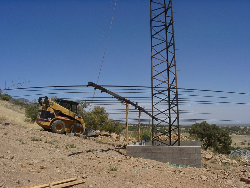
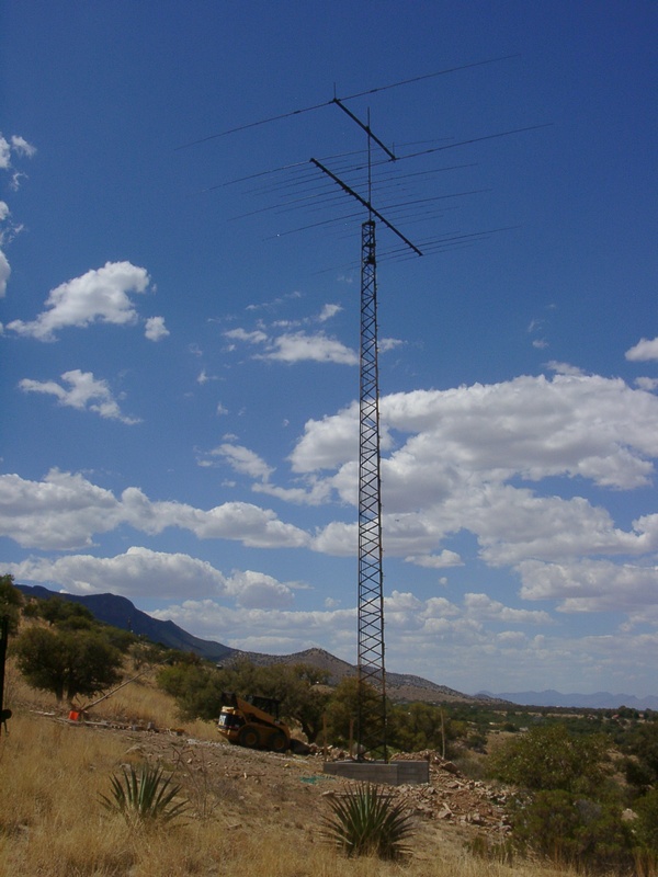
In the end, everything went according to plan and I was able to mount the OB16-3 where I wanted it on the mast. The OB2-40 is at 25m above the ground, and the OB16-3 is at 22m. Both are excellent antennas and I have had extremely promising results with them in the short time I have used them. When I get the chance I will try to run some polar response plots and add them to the web site.
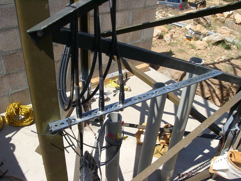
The feedlines and control lines are only temporarily in place in this picture. I barely was able to get everything functional for the 2008 CQ WPX CW contest and didn't have time to dress all the runs properly, but you can see here the feedline bulkhead at the base of the tower, and there is an identical one at the top of the tower. Hopefully they will help to bypass to ground any induced shield currents.
AB7E Home
Tower and Antenna Project Home
Previous Page Next Page

The elements attach quite easily to the boom. Each element has a center section that mounts into its respective saddle, and then the outer portions of each element are inserted into those. I used a lubricating anti-oxidant on all joints, and spray painted the elements and boom after everything was in place.
The base of the HD-70 tower is 48 inches across at the base, which forced me to initially omit two of the elements (a 20m director and a 10m director) since there otherwise would not have been enough space between elements for the tower. I hoisted the antenna up to the mast by hand using the same rope and pulley system you can see in the background, and then installed those two directors at the top of the tower. I'm fairly fit, but the OB16-3 weighs about 100 pounds and it was a major physical effort to raise it up with the cheap pulleys I used. My wife and son again handled the tag lines at the ends of the boom, and they did an excellent job keeping both the boom and the elements away from the tower.
In the end, everything went according to plan and I was able to mount the OB16-3 where I wanted it on the mast. The OB2-40 is at 25m above the ground, and the OB16-3 is at 22m. Both are excellent antennas and I have had extremely promising results with them in the short time I have used them. When I get the chance I will try to run some polar response plots and add them to the web site.
The feedlines and control lines are only temporarily in place in this picture. I barely was able to get everything functional for the 2008 CQ WPX CW contest and didn't have time to dress all the runs properly, but you can see here the feedline bulkhead at the base of the tower, and there is an identical one at the top of the tower. Hopefully they will help to bypass to ground any induced shield currents.
AB7E Home
Tower and Antenna Project Home
Previous Page Next Page